WiiBoy rev3 – it’s finished

The WiiBoy rev3 has reached a very stable point where I’m happy to call it finished. Casting the case turned out to be difficult and I’m not ready for it so the case was professionally printed by Shapeways with their nylon powder services. The finish has some printed artifacts (much less than standard PLA FDM) but it is incredibly soft and smooth.

20190502_183621.jpg

The internals are my best. The use of 7 custom pcbs greatly eliminates a lot of wiring. Although I spent months designing the case and pcbs, the assembly is very quick now.

20190501_071300

Some may criticize the standard Wii trim and how I could’ve fit more batteries, but I love the neatness and cleanliness of the wiring. Also using 2 battery cells allowed me to design better shoulder buttons which is a challenge to pull off on a portrait style handheld.

20190527_144601.jpg

The USB-C features are still my favorite part. The pcb turned out to be pretty universal and I’m reusing the USB-C assets in other projects now.

Maybe later this year after GC+ 2.0 is released, I’ll certainly be redesigning the controller pcb for a WiiBoy rev4. I can try to push the custom pcbs to be even more integrated by reducing the number of pcbs and using some FFC cables for the inter-connections. But for now I’ll focus on other projects like the summer portablizing competition.


Wii PMS for sale!

20190417_091005.jpg

After making my Wii PMS project open source on github, I was humbled by all the emails from people asking to buy it even though they had the resources to build it themselves, you guys rock. It is now for sale on the BitBuilt store. https://store.bitbuilt.net/wii-power-management-system-pre-order/

The first batch is of 15 units, we will be gauging the demand and make more if the interest is there. Buy them while stock lasts! Each one is fully assembled, programmed, and tested for all 5 regulators (1v, 1.15v, 1.8v, 3.3v, and 5v) and includes the thermistor for thermal protection.


The WiiVision

The WiiVision is a tribute to one of my favorite Gamecube portables, the Envision, made by Jonathon Shine in 2011.

envision

Just so happens that the Envision was a tribute to one of his favorite N64 portables, The Sixty Free Lite-R made in 2009 by Sifuf.

sixtyfreemain

The WiiVision was a collaboration with one of my buddies Shank. We started the project in 2017 but abandoned it for a while as we moved on to other projects. In January this year, I went down to Texas for a week to visit Shank and we planned to finish 2 WiiVisions. We didn’t finish either of them but we got close and finished it soon after I got back.

20190108_081007

The build uses mostly off the shelf components so it’s simple to put together.

20190104_233622

It uses my new Wii PMS pcb which I recently made open source.

The WiiVision is a solid portable. The use of original analog triggers is not something we often see in projects anymore but it is so worth it. I’m now working on a second WiiVision on commission. It’ll be almost the same but with some small improvements like using Joycon joysticks and a WiiHUD audio amplifier. It should be complete in a few weeks.


Wii Power Management System is now Open Source!

20190102_154619.jpg

https://github.com/Gmanmodz/Wii-Power-Management-System

My Wii PMS pcb files, code, and bill of materials is now available to download for free on my github! This is an all-in-one system for battery charging, battery protection, Wii custom regulators, and more. The parts can be ordered from digikey for just under $30 and the 4layer pcb can be acquired cheaply from JLCpcb, OSHpark, and others.

Portablizing has been plagued for years from inefficient buck regulators, expensive smart lithium-ion chargers, and poor quality Chinese battery charging pcbs. This pcb will solve many problems we faced previously while also having a more integrated user-interface.

Features:

4 buck regulators – 1v, 1.15v, 1.8v, and 3.3v
1 boost regulator – 5v
Battery management IC – seamless play and charge and battery protection
PIC microcontroller for enabling the regulators, programming the battery IC registers, reading battery statuses, thermal protection, and other tasks

Interface:
hold down button for around 1 second to turn on and off. Tap button shortly to cycle through the led modes:
1. leds off
2. RGB fade
3. Battery monitor
4. Shipping mode (when it is turned off in this mode, it cannot be turned on until you plug in a charger)

It’s not perfect by any means but it is stable and has already been installed working in 3 portables. I would like to thank Aurelio for the answers to many questions I had over the past 2 years I’ve worked on this and also for the inspiration from his Powermii. I’d also like to thank Shank for helping me test it further on the Wiivision project.

USB-C PD DEEP DIVE

USB-C charging in portables is just awesome, though it is a bit more involved than traditional charging methods. I’ll walk you through how you too can enjoy this awesome feature.

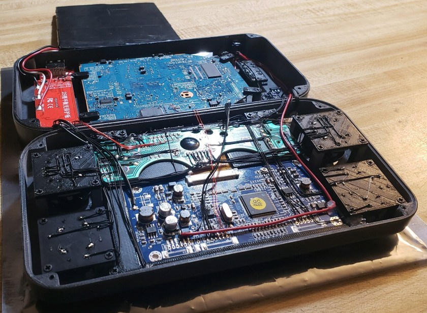
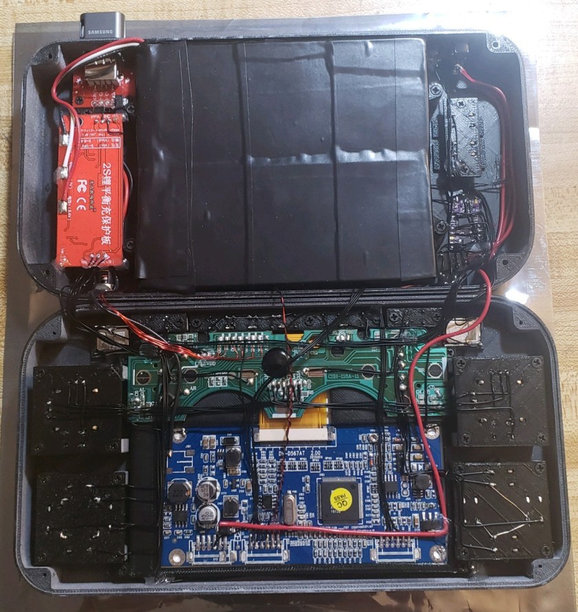
The STUSB4500 is a nice little IC for power-delivery negotiation. It requires few additional components to get working and it runs autonomously with little software intervention on our part. This chip is ideal for a battery powered, space limited, portable application.

Note: USB-C PD only negotiates a higher VBUS voltage, it can not be used to directly charge the batteries, you will also need a lithium-ion smart charging circuit.

stusb4500

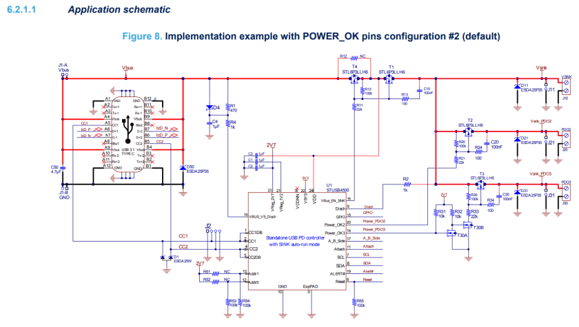
This application schematic provides everything you need to get the chip started. If we want an internal usb drive accessible over the USB-C port, we’ll need to do some more work.

  1. USB-C PD can source up to 20V on VBUS, we’ll need a VBUS to 5V step-down regulator for powering the USB drive. Make sure the buck regulator can do 100% PWM in case the VBUS is only negotiated to 5V.
  2. A USB 2.0 data multiplexer for switching the USB drive data lines between the Wii and the USB cable. You might need a small linear regulator for powering this IC so the data lines can still be switched when the portable is turned off.
  3. A power multiplexer for switching power to the USB drive between the VBUS step-down, and the 5V regulator already in the Wii portable. This is required because the USB drive needs to be powered when the portable is off and when the USB cable is plugged in.

usb

Note: I chose to power the 3.3V LDO from the 5V power multiplexer so it will be powered when the portable is off (cable plugged in). If you’re confident that the multiplexer can be put into a low power mode, then it might be possible to power it from our battery system voltage and skip the LDO entirely.

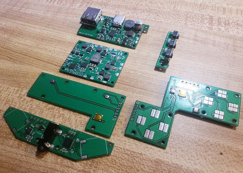
The VBUS step down converter I chose might have been a little overkill (it has a maximum input voltage of 36V!). If I redesign this schematic, I’d probably go with one that has a smaller PCB footprint. Though it proves to work fine.

pd

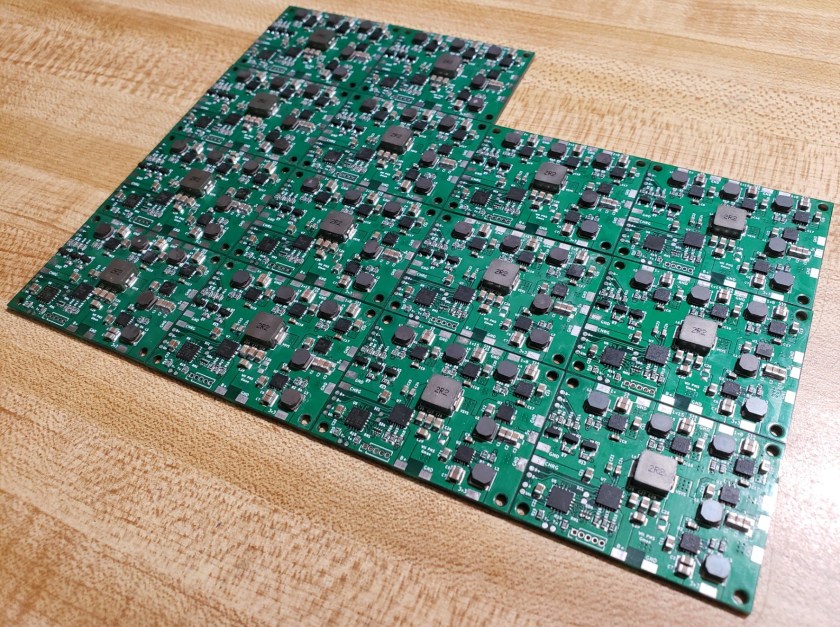
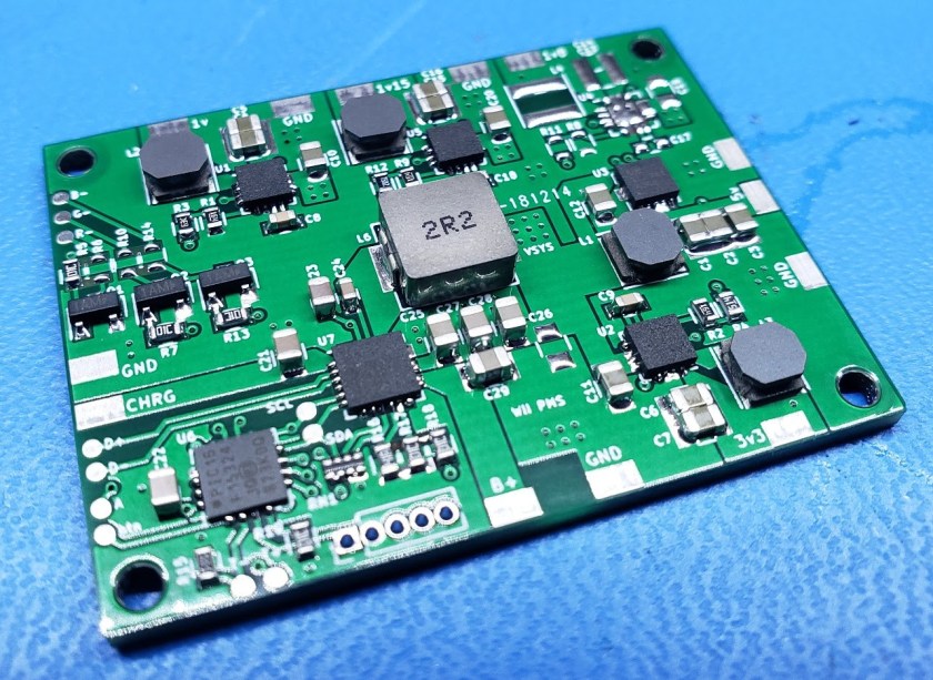
The layout can be condensed pretty small! I did make one minor mistake in this, the silkscreen for C10 is backwards, oops. I just have to remember that when I assemble it. Also the labels for the input pads aren’t exactly correct, the pad labeled 3v3 actually needs to go to the battery system voltage. The IO core of the STUSB4500 needs to share the same I2C voltage as our microcontroller. Lastly “S”, the multiplexer select is chosen to be wired to any of our system voltage regulators so that way the USB drive is always connected to the Wii when the portable is turned on.

This PCB will work as is, that is if you are fine with negotiating to the maximum power the charger you plug in can provide. My battery charger can only accept an input voltage max of 14V, if we use a 20V USB charger, this will not do. We will need a microcontroller to program the Power Delivery Objects (PDO) through the I2C registers.

regstusb

Here are the necessary register addresses of the STUSB4500 taken from the datasheet. The values to set them are not so clear, but it is possible to figure it out by piecing it together from the example code they provide. I had some help from my buddy Aurelio, who guided me through setting the registers.

The key is that the PDO voltage and current are 10-bit parameters stored in 8-bit registers in little endian format.

stusbcode1

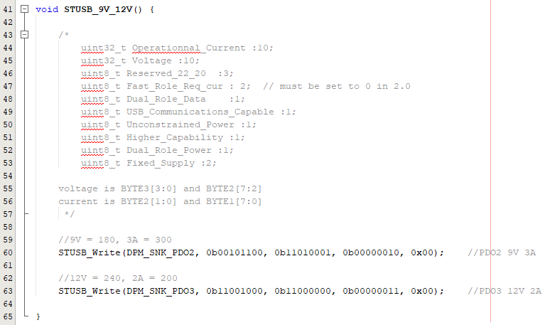
STUSB_Write(), is a function I wrote to condense the basic I2C commands for setting the STUSB4500 to output either 12V, 9V, or 5V.

20190122_145437.jpg

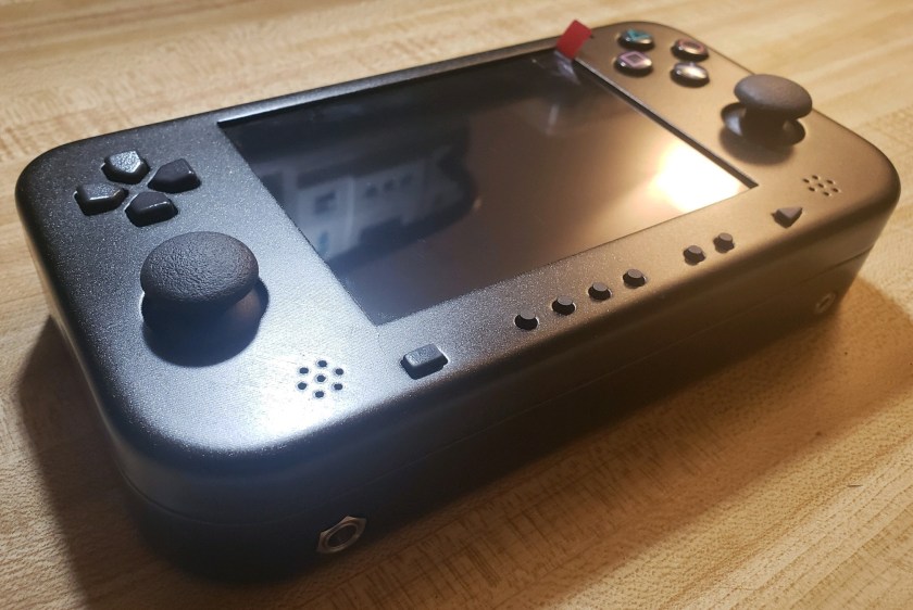
It even works with the Nintendo Switch charger, Nice!

WiiBoy rev3 Progress

20190210_145143

To prepare for getting the casing casted, I thought it would be a good idea to build up a functional prototype for testing. I’m starting to feel the WiiBoy magic.

20190210_113543

Even though this model only uses 2 battery cells, there is not too much empty space. I even had to sand the USB drive down to fit.

20190210_121015

Using only 2 battery cells also has its advantage that the Wii doesn’t have to be trimmed so small, improving the reliability.

Notice the small bead and blue wire on the Wii? It’s a temp sensor probe. I added thermal protection in the firmware which shuts the console down if the temperature rises above 75C. It shouldn’t ever get close to that in normal conditions but in the situation where the console accidentally turns on in a bag (or during shipping), it’ll prevent it from melting down.

20190211_111224

But perhaps the greatest improvement from a small sacrifice of the battery size are the improved shoulder buttons. They are in the perfect spot when you hold it.

Well it looks like the WiiBoy is mostly done? Nope, this is just a thorough prototype. The real fun will begin soon..

PCBs, PCBs, PCBs

20190122_222756

Pictured above is all the PCBs for my new shiny WiiBoy I’ve been working on. I ordered them from JLCPCB (which has been a really great service so far). I used a solder template and placed the components by hand before using a hot air station to reflow it.

The most exciting pcb (in my opinion), is the one on the very top, it’s a USB-C Power Delivery and Data Multiplexer. In other words, it allows me to charge the batteries and use an internal usb drive all through the one USB-C port. I haven’t tested all the functions yet but I did successfully negotiate 15v out of a USB-C charger so I consider that success for now.

usbc.png

It’s a 4 layered PCB which I’ve had to do a few times now so I’m starting to get the hang of it.

solidworks.png

Well the design is going great so far. Hopefully the testing of the PCBs will go smoothly. On track for an MGC release…

A Brief History of the WiiBoy

Some would argue that the WiiBoy first began as far back as 2013 during my very first GameCube portable called the “DMG Cube”. Fitting a GameCube in a DMG housing was no easy walk in the park even without internal batteries. The DMG Cube was sold and has past through various owners over the years. Believe it or not, it’s still in excellent working condition after it popped up for sale on Ebay earlier this year.

dmgcube.png

Moving on, the WiiBoy is one of my oldest and on-going projects. Taking root in April 2016 for the BitBuilt Summer 2016 modding competition, the WiiBoy would be a Wii inside a DMG gameboy housing with batteries.

13244670_1322048521143277_7534326495399545897_n

Rev1 was finished in about 3 months but I wasn’t entirely satisfied with it. Still time left in the competition, I began the WiiBoy rev2 taking into account what I learned from the first model to improve the heatsink and overall quality.

DSC_0047_zpsa2skdcy3.JPG

Rev2 was cleaner all around and after accomplishing the “LMAO” Wii trim, it had room for double the batteries of the first one.

IMG_20160720_225234856_HDR_zpsq6eoym4w

The WiiBoy rev2 was voted first place in the 2016 Summer competition, a time where custom pcbs were still nonexistent in the modding community. Oh the times have changed.

January 2018, In preparation for my MGC (Midwest Gaming Classic) display, I decided to make an appearance with a brand new WiiBoy rev3. This one was designed again from the ground up utilizing 3D printing and custom pcbs. My modding buddy Chris Downing was nice enough to lend me his fancy Form 2 SLA printer to attempt and achieve an OEM looking console. With only a few weeks left before the convention, I rushed out the pcbs and threw together a prototype WiiBoy rev3. It wasn’t perfect by any means but it definitely caught some eyes at MGC.

20180413_151257.jpg

The WiiBoy rev3 at MGC alongside the PiiWii Pocket, GS2, and an N64 portable I have not yet unveiled for some reason.

MGC came and went and I could not get the amazing quality of the Form 2 out of my head so I purchased the new AnyCubic Photon resin printer. Boy I had no idea what I had gotten myself into. Turns out low power resin has awful warping qualities on large prints and after throwing money at various different resin brands, I failed at getting any passable case from the investment. The printer had failed the WiiBoy although it was still a great learning experience and I certainly don’t regret it.

20180324_180008.jpg

The WiiBoy continuously challenges me and for that it holds a special place in my heart. There is no doubt it will be seen again, maybe even at MGC 2019…


Last commissions of the year completed!

20181209_152418.jpg

It’s been a busy few weeks to get these 2 PS2 portable commissions completed and shipped for Christmas. It helps that they are both the same unit but the case work painting was intensive on both of them. Anyway they turned out really slick and clean, possibly my best units so far.

20181207_183844.jpg

20181209_141414.jpg

The wiring is very dense but I tried to keep it as neat as possible. It’s wired in a way so that I can bend the motherboard over to access both sides of it. Same for the battery, it can be moved out of the way to wire the next part. The result keeps it neat and manageable to repair if ever needed. I hope the customers enjoy them!

Improving the “Improved PS2 Portable”

One of the reasons why I don’t do many completely unique commissions anywhere is because sticking with the same design gives you the opportunity to make iterations and really fine tune your design into a solid product.

About a year ago I came out with my “flagship” PS2 portable for commissions. Since then, I’ve built several of them and I am now starting my 3rd iteration of the design for my latest commission.

Most of the changes are minor internal changes for mechanical strength like the new screw posts. The previous models used screw pegs that extrude from the top half of the device all the way to the back of the device. I’ve changed it for a buried screw type post. The post uses the strength of the case instead of relying on a tall screw peg that can snap in half if over tightened. ps2screw

Looking at the front half of the assembly, everything is now mounted with screws which are far cleaner and less likely to fail than various glues. There is simplicity in a build with no custom PCBs. I’m enjoying it while it’s still acceptable to do because it drastically decreases the development time and complexity. Besides, it is a tried method and very unlikely to fail without the additional electronics.

ps2top

Finally, I have made one external aesthetic change, swapping the start/select controller buttons from the buttons from an actual PS2 controller. It gives it a more Sony vibe. Now it’s time to get building. There are a few more improvements to it but I’ll talk about those if I can have this one wrapped up in a few weeks.

ps2outside