USB-C charging in portables is just awesome, though it is a bit more involved than traditional charging methods. I’ll walk you through how you too can enjoy this awesome feature.
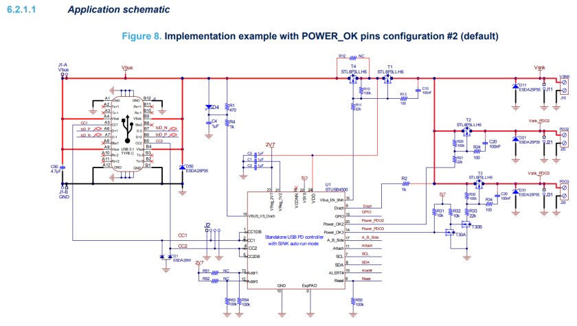
The STUSB4500 is a nice little IC for power-delivery negotiation. It requires few additional components to get working and it runs autonomously with little software intervention on our part. This chip is ideal for a battery powered, space limited, portable application.
Note: USB-C PD only negotiates a higher VBUS voltage, it can not be used to directly charge the batteries, you will also need a lithium-ion smart charging circuit.

This application schematic provides everything you need to get the chip started. If we want an internal usb drive accessible over the USB-C port, we’ll need to do some more work.
- USB-C PD can source up to 20V on VBUS, we’ll need a VBUS to 5V step-down regulator for powering the USB drive. Make sure the buck regulator can do 100% PWM in case the VBUS is only negotiated to 5V.
- A USB 2.0 data multiplexer for switching the USB drive data lines between the Wii and the USB cable. You might need a small linear regulator for powering this IC so the data lines can still be switched when the portable is turned off.
- A power multiplexer for switching power to the USB drive between the VBUS step-down, and the 5V regulator already in the Wii portable. This is required because the USB drive needs to be powered when the portable is off and when the USB cable is plugged in.

Note: I chose to power the 3.3V LDO from the 5V power multiplexer so it will be powered when the portable is off (cable plugged in). If you’re confident that the multiplexer can be put into a low power mode, then it might be possible to power it from our battery system voltage and skip the LDO entirely.
The VBUS step down converter I chose might have been a little overkill (it has a maximum input voltage of 36V!). If I redesign this schematic, I’d probably go with one that has a smaller PCB footprint. Though it proves to work fine.

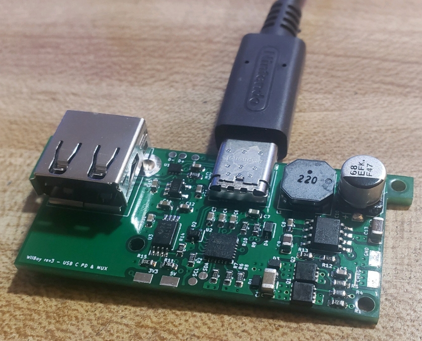
The layout can be condensed pretty small! I did make one minor mistake in this, the silkscreen for C10 is backwards, oops. I just have to remember that when I assemble it. Also the labels for the input pads aren’t exactly correct, the pad labeled 3v3 actually needs to go to the battery system voltage. The IO core of the STUSB4500 needs to share the same I2C voltage as our microcontroller. Lastly “S”, the multiplexer select is chosen to be wired to any of our system voltage regulators so that way the USB drive is always connected to the Wii when the portable is turned on.
This PCB will work as is, that is if you are fine with negotiating to the maximum power the charger you plug in can provide. My battery charger can only accept an input voltage max of 14V, if we use a 20V USB charger, this will not do. We will need a microcontroller to program the Power Delivery Objects (PDO) through the I2C registers.

Here are the necessary register addresses of the STUSB4500 taken from the datasheet. The values to set them are not so clear, but it is possible to figure it out by piecing it together from the example code they provide. I had some help from my buddy Aurelio, who guided me through setting the registers.
The key is that the PDO voltage and current are 10-bit parameters stored in 8-bit registers in little endian format.

STUSB_Write(), is a function I wrote to condense the basic I2C commands for setting the STUSB4500 to output either 12V, 9V, or 5V.

It even works with the Nintendo Switch charger, Nice!
