
The Sega Dreamcast uses a proprietary digital protocol called the “Maple Bus”. It is a unique two-wire bi-directional signal where each data line alternates between taking the task of data and clock every other bit — woah.
When using common protocols like UART, I2C, SPI, etc these protocols are handled in hardware circuitry built inside the microcontrollers usually. Then the C code simply refers to the transmit / receive buffers along with the flags. This is ideal since the code does not have to be stalled during transmission and can focus on more pressing tasks.
However, the Maple bus is proprietary so you won’t find any microcontroller with a hardware Maple peripheral. You could use an FPGA, but I chose to use a microcontroller instead. Thus bit banging is required, where the protocol is implemented in software.
A Maple transmission is begun by a starting sequence to initiate the transmission. Both data lines start at the high position, data 1 is pulled low and remains low. Then data 2 is pulsed 4 times and holds high. Then data 1 goes high and data 2 is pulled low again. Data 1 is high and data 2 is low, this is how each 2-bit phase begins.
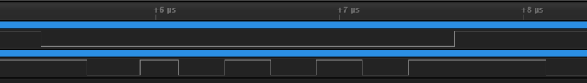
Here is the starting sequence captured by a logic analyzer.
A byte is transmitted in 4 2-bit phases. Phase 1: Data 1 is high, data 2 is low. Data 2 transitions to the level of the bit to be transmitted. Data 1 then pulls low and the bit is clocked in. Then data 1 transitions to the next bit and data 2 is pulled low, clocking in the bit. The phase is complete and it starts over again. Since data is always clocked in on the opposite data line of a falling edge, we really don’t need to keep track of the phases after the starting sequence, we just need to look for the falling edges.

Example: “0b00011100”.
Since data is transmitted at 1MB/S, I will need to choose a fast microcontroller that will be able to accurately sample the bits. I went with the PIC32MZ as I had some prior experience with that microcontroller for another project. The PIC32 can have a maximum CPU clock of 200MHz, estimating that an instruction can be executed on each clock (which isn’t always true), then I will be left with 200 instructions to sample each bit — even with my poor amateur code, it should be do-able!
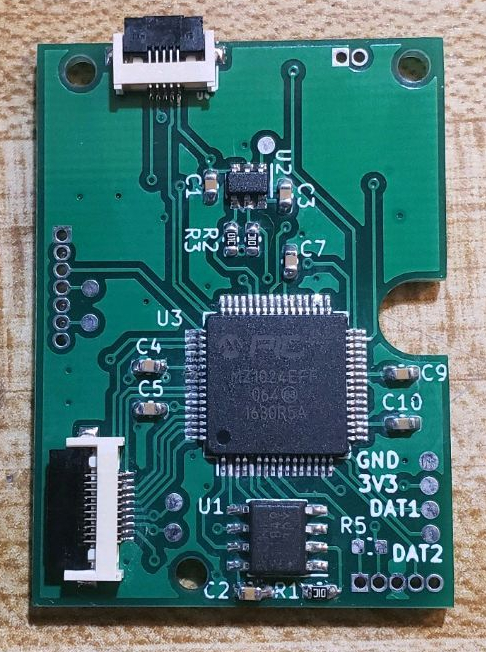
The custom controller PCB I designed with the PIC32 and some additional hardware to be used later for the VMU emulation like the FRAM chip and OLED screen.
First I implement the transmitting code.
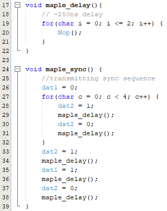
The maple_delay() function will be used for timing throughout the rest of the code. This is pretty easy so far, setting the data lines high and low to match the original controller.
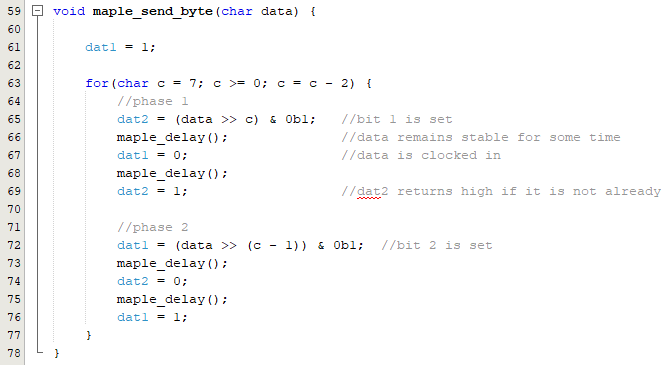
Sending one byte of data meticulously through the phases.
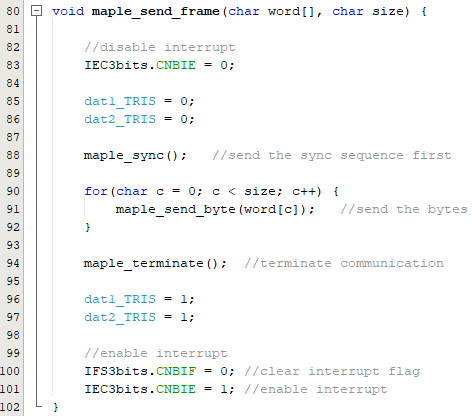
Finally the basic bit functions can be sorted together to send an entire word (4 bytes)!
With the transmitting done and out of the way, time to figure out how the heck I will handle receiving bits. I can’t just sample the data lines forever in a loop because the microcontroller needs to handle other tasks like sampling the controller buttons, joystick ADC, and formulating the response packet.
After trying several methods out, the way it worked reliably enough was to capture the starting sequence using an interrupt flagged from the falling edges of the data lines. When the starting sequence is matched to be true, it disables the interrupt and samples the bits in a loop until the entire word is received. I’m not too happy about this method because it is limiting and the CPU is stalled during the entire receiving transmission. It is also very memory hungry, needing to sample each falling edge and then package the data into the bytes they belong afterwards. But I digress, it works reliably enough for a playable controller. There’s nothing ideal or perfect about bit banging a protocol in software anyway.
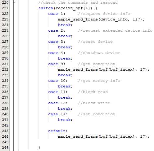
With the protocol implemented, the controller commands can be sampled and responded with the correct packet response. I only have two commands implemented for basic functionality controller. The other commands are for VMU which is currently not implemented at all, I will need a more robust receiving protocol before I tackle that since many more words will need to be accurately sampled one after another.
The software has a ways to go, but I’m pleased that I was able to get it working this far. I certainly learned a lot through this project.
https://github.com/Gmanmodz/Dreamcast-Controller-Emulator
The Dreamcast controller emulator can be seen in action on my latest portable, the 2DC!

Dam good job man. I just got through emulating the NES, SNES, Genesis, Saturn, TurboGrafx16, and Gamecube controllers. I think Dreamcast is next but I heard of its crazy sounding protocol. Even though I’ll be using an STM32 at 168MHz, I think it can be done. Thanks for this page and the github code. It’ll be a great reference!
LikeLike